CES 2015: Data Analytics Lend Wireless Sensors Power to Change Lives

davidallan_virtuix

By David Allan, President, Virtuix Inc.

Walking the aisles at CES, you are hard-pressed to find a single product that doesn’t contain at least one sensor. The latest iPhones add a barometric sensor to at least a dozen others. By some predictions, a trillion-sensor world is not far off. Yet what benefits, really, will this ubiquity of sensors deliver? We put this question, and others, to the speakers at the Sensors and MEMS Technology conference.

To Karen Lightman, Executive Director of the MEMS Industry Group, the answer lies in pairing sensors with data analytics. She notes that “MEMS and sensors are already fulfilling the promise to make the world a better place, from airbags and active rollover protection in our cars to the smart toaster that ensures my daughter’s morning bagel won’t be burnt. By combining sensors with data analytics, we can increase that intelligence exponentially.”

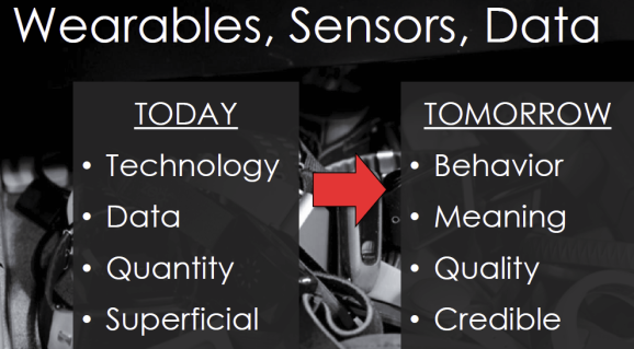
An example is biometric measurements, which traditionally suffer from undersampling. Your doctor checks your pulse or blood pressure just once in a while, whereas a typical day may see wild fluctuations. David He, Chief Scientist at Quanttus Inc., predicts a convergence between consumer and clinical use of wearable sensors. Noting that cardiovascular disease and other chronic conditions often go undiagnosed, he foresees ICU-quality wearable sensors that measure your vital signs as you undergo daily activities, relying on enormous datasets to detect problematic patterns. “While everyone is looking for the killer app in wearables,” he urges, “we should be looking for the un-killer app.”

virtuix_graphic

Date analytics paired with ubiquitous sensors promise to improve and even save lives (Image courtesy of Quanttus Inc.)

Ben Waber, CEO of Sociometric Solutions, puts sensor data to a radically different use. His firm outfits employees of large companies with sensor-equipped badges that track their interactions. “In any industry the interaction between employees is the most important thing that happens at work,” he told CNN. His badges use motion sensors to follow users as they mix with others in the office and to monitor their posture while seated (slouching suggests low energy). A microphone measures tone of voice, rapidity of speech, and whether a person dominates meetings or allows others to speak in turn.

Waber claims employees can use the results to improve performance and job satisfaction. “You can see the top performers and change your behavior accordingly, to be happier and more productive. In a retail store, you might see that you spend 20% of your time talking to customers, but the guy who makes the most commission spends 30%.” He adds, “I can point to thousands of people who say they like their jobs better.”

Steven LeBoeuf, president of Valencell, points to a problem he calls “death by discharge,” meaning the tendency of novel wearables to “land in the sock drawer before insights can be made” because users tire of keeping them charged. His firm promotes a category he calls “hearables”: sensors added to earphones—powered from a standard jack—that measure pulse, breathing, blood pressure, and even blood-oxygen saturation, all from gossamer-thin vessels on the ear called “arterioles.” Yet measurements alone, he cautions, fall short without comparative analytics. “Human subject testing is a different animal altogether…extensive human subject validation is required for accurate biometric sensing.”

Data is moving from physical to mental. Rana el Kaliouby’s company, Affectiva, combines sensor data with analytics to monitor emotional states, detecting stress, loneliness, depression, and productivity. She foresees a sensor-driven “emotion economy” where devices act on our feelings. She told The New Yorker, “We put together a patent application for a system that could dynamically price advertising depending on how people responded to it.”

Indeed, patent filings abound for mood-sensing devices. Anheuser-Busch’s application for an “intelligent beverage container,” notes that without it, sports fans at games “wishing to use their beverage containers to express emotion are limited to, for example, raising a bottle to express solidarity with a team.”

Now stonily indifferent to our feelings, our devices may acquire an almost-human sympathy. “I think that, ten years down the line,” predicts Affectiva’s Kaliouby, “we won’t remember what it was like when we couldn’t just frown at our device, and our device would say, ‘Oh, you didn’t like that, did you?’”

Building a virtual gyro

Originally posted by Michael E Stanley of Freescale Semiconductor in The Embedded Beat on Mar 12, 2013

In Orientation Representations Part 1 and Part 2, we explore some of the mathematical ways to represent the orientation of an object. Now we’re going to apply that knowledge to build a virtual gyroscope using data from a 3-axis accelerometer and 3-axis magnetometer. Reasons you might want to do this include “cost” and “cost”. Cost #1 is financial. Gyros tend to be more expensive than the other two sensors. Eliminating them from the BOM is attractive for that reason.  Cost #2 is power. The power consumed by a typical accel/mag pair is significantly less than that consumed by a MEMS gyro. The downside of a virtual gyro is that it is sensitive to linear acceleration and uncorrected magnetic interference. If either of those is present, you probably still want a physical gyro.

So how do we go from orientation to angular rates? It’s conceptually easy if you step back and consider the problem from a high level. Angular rate can be defined as change in orientation per unit time. We already know lots of ways to model orientation. Figure out how to take the derivative of the orientation and we’re there!

In our prior postings, we’ve discussed a number of ways to represent orientation. For this discussion, we will use the basic rotation matrix. Jack B. Kuipers has a nice derivation of the derivative of direction cosine matrices in his “Quaternions and Rotation Sequences” text – one of my most used textbooks.  It makes a good starting point.  Paraphrasing his math:

Let:

  1. vf = some vector v measured in a fixed reference frame
  2. vb = same vector measured in a moving body frame
  3. RMt = rotation matrix which takes vf into vb
  4. ω = angular rate through the rotation

Then at any time t:

  1. vb= RMt vf

Differentiate both sides (use the chain rule on the RHS):

  1. dvb/dt  = (dRMt/dt) vf + RMt(dvf /dt)

Our restrictions on no linear acceleration or magnetic interference imply that:

  1. dvf/dt = 0

Then:

  1. dvb/dt  = (dRMt/dt) vf

We know that:

  1. vf = RMt-1 vb

Plugging this into (8) yields

  1. dvb/dt  = (dRMt/dt) RMt-1 vb

In a previous posting (Accelerometer placement – where and why) , we learned about the transport theorem, which describes the rate of change of a vector in a moving frame:

dvf/dt = dvb/dt – ω X vb

Those who take the time to check will note that we have inverted the polarity of the ω in Equation 11 from that shown in the prior posting.  In that case ω was the angular velocity of the body frame in the fixed reference frame.  Here we want it from the opposite perspective (which would match gyro outputs).

And again,

  1. dvf/dt = 0 so
  2. dvb/dt = ω X vb

Equating equations 10 and 13:

  1. ω X vb = (dRMt/dt) RMt-1vb
  2. ω X = (dRMt/dt) RMt-1

where:

  1. 0 z ωy
    ω X = ωz 0 x
    y ωx 0

Going back to the fundamentals in our first calculus course and using a one-sided approximation to the derivative:

  1. dRMt/dt = (1/Δt)(RMt+1 – RMt)

where Δt = the time between orientation samples

  1. ωb X = (1/Δt)(RMt+1 – RMt) RMt-1

Recall that for rotation matrices, the transpose is the same as the inverse:

  1. RMtT = RMt-1
  2. ωb X = (1/Δt)(RMt+1 – RMt) RMtT

Equation 15 is a truly elegant equation.  It shows that you can calculate angular rates based upon knowledge of only the last two orientations.  That makes perfect intuitive sense, and I’m ashamed when I think how long it took me to arrive at it the first time.

An alternate form that is even more attractive can be had by carrying out the multiplications on the RHS:

  1. ωb X = (1/Δt)(RMt+1 RMtT – RMt RMtT)
  2. ωb X = (1/Δt)(RMt+1 RMtT – I3×3)

For the sake of being explicit, let’s expand the terms.  A rotation matrix has dimensions 3×3.  So both left and right hand sides of Eqn. 22 have dimensions 3×3.

  1. (1/Δt)(RMt+1 RMtT – I3×3)  = (1/Δt) W
  1. 0 W1,2 W1,3
    W = RMt+1 RMtT – I3X3 = W2,1 0 W2,3
    W3,1 W3,2 0

The zero value diagonal elements in W result from small angle approximations since the diagonal terms on RMt+1 RMtT will be close to one, which will be canceled by the subtraction of the identity matrix.  Then:

  1. 0 z y 0 W1,2 W1,3
    ω X = z 0 x =  (1/Δt) W2,1 0 W2,3
    y x 0 W3,1 W3,2 0

and we have:

  1. ωx= (1/2Δt) (W3,2 – W2,3)
  2. ωy= (1/2Δt) (W1,3 – W3,1)
  3. ωz= (1/2Δt) (W2,1 – W1,2)

Once we have orientations, we’re in a position to compute corresponding angular rates with

  • One 3×3 matrix multiply operation
  • 3 scalar subtractions
  • 3 scalar multiplications

at time each point.  Sweet!

Some time ago, I ran a Matlab simulation to look at outputs of a gyro versus outputs from a “virtual gyro” based upon accelerometer/magnetometer readings.  After adjusting for gyro offset and scale factors, I got pretty good correlation, as can be seen in the figure below.

image001.gif

You will notice that we started with an assumption that we already know how to calculate orientation given accelerometer/magnetometer readings.  There are many ways to do this.  I can think of three off the top of my head:

  • Compute roll, pitch and yaw as described in Freescale AN4248.  Use those values to compute rotation matrices as described in Orientation Representations: Part 1.  This approach uses Euler angles, which I like to stay away from, but you could give it a go.
  • Use the Android getRotationMatrix [4] to compute rotation matrices directly.  This method uses a sequence of cross-products to arrive at the current orientation.
  • Use a solution to Wahba’s problem to compute the optimal rotation for each time point.  This is my personal favorite, but I think I’ll save further explanation for a future posting.

Whichever technique you use to compute orientations, you need to pay attention to a few details:

  • Remember that non-zero linear acceleration and/or uncorrected magnetic interference violate the physical assumptions behind the theory.
  • The expressions shown generally rely on a small angle assumption.  That is, the change in orientation from one time step to the next is relatively small.  You can encourage this by using a short sampling interval.  You should soon see an app note that my colleague Mark Pedley is working on that discards that assumption and deals with large angles directly.   I like the form I’ve shown here because it is more intuitive.
  • Noise in the accelerometer and magnetometer outputs will result in very visible noise in the virtual gyro output.  You will want to low pass filter your outputs prior to using them.  Mark will be providing an example implementation in his app note.

This is one of my favorite fusion problems.  There’s a certain beauty in the way that nature provides different perspectives of angular motion.  I hope you enjoy it also.

References

  1. Freescale Application Note Number AN4248: Implementing a Tilt-Compensated eCompass using Accelerometer and Magnetometer Sensors
  2. Orientation Representations: Part 1 blog posting on the Embedded Beat
  3. Orientation Representations: Part 2 blog posting on the Embedded Beat
  4. getRotationMatrix() function defined at http://developer.android.com/reference/android/hardware/SensorManager.htmlWikipedia entry for “Wahba’s problem”
  5. U.S. Patent Application 13/748381, SYSTEMS AND METHOD FOR GYROSCOPE CALIBRATION, Michael Stanley, Freescale Semiconductor

See you at CES!

MIG looks forward to advancing MEMS across global markets at next week’s 2012 International CES®.  It’s not too late to make your plans to attend!
MEMS TechZone

LVCC, South Hall 2, Booth #25218
January 10 – 13, 2012

Stop by the booth to register to win MOD Live from Recon Instruments (winner of the 2011 MEMS Technology Showcase at MEMS Executive Congress®) and see the VGo Robotic Telepresence (enabled by MEMS developed by Freescale Semiconductor.)

Recon Instruments VGo
 

MEMS Conference Session

Connecting the Real World with the Digital World: Harnessing the Power of MEMS
LVCC, North Hall, Room N254
January 11, 2012 | 10:30-11:30am
Spread the word to your colleagues and customers to attend this much anticipated session. In this session, you’ll earn how MEMS is truly driving the adoption of new consumer applications and products.

TechZone Participants and Sponsors


Complimentary MIG Networking Breakfast

Sponsored by 

STMicroelectronics

Conference Room 7, Second Floor, Las Vegas Hilton
January 11, 2012 | 7:00-9:00 am

Join press and members of MIG for a complimentary continental breakfast and networking time. (RSVP required)

MEMS at 2012 CES® PressroomIf you can’t make it to the show, be sure to check out the latest press releases related to MEMS at 2012 CES® in our online press room.  MIG members, if you are attending the show and have a press release, make sure to send it to Kacey Wherley at kwherley@memsindustrygroup.org for inclusion.

See you in Las Vegas!